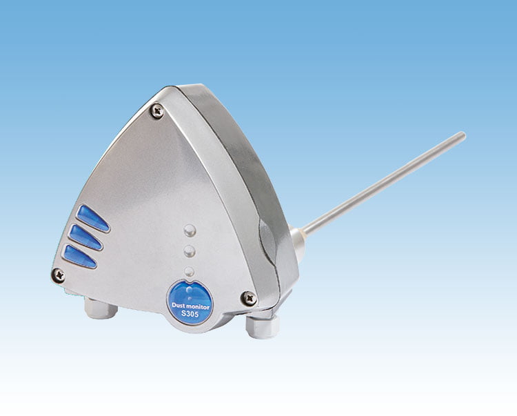
QAL1 certified stack monitor for official emissions measurements
QAL1 certified by TUV to meet the EN 14181 standard, the S305 dust monitor is used for official emissions applications. The state of the art dust monitor has been used in stack emissions for a number of state owned and private industrial applications around the world.
Utilizing our unique Inductive Electrification principle, the S305 brings the reliability the government requires and combines it with the convenience plant operators expect from a particulate measurement device. With minimal maintenance required, this is an optimal solution for plant operators needing to measure stack dust emissions for government control..
ATEX Models
- Certified for ATEX Zone 20, 21 or 22
- Approved to Category II 1/2 for Gas and Dust
- IP65 Enclosure, Custom Designed ● Certification Type: II 1/2 GD EEx ia IIC, T6, IP65, 85°C
- Utilizing SINTROL’s Advanced Inductive Electrification Technology
The ATEX directive covers health and safety of workers potentially at risk from exposure to explosive environments. This directive classifies areas into Zone 0, 1, 2 for gas and 20, 21 or 22 for dust and guides plant operators to install the appropriate ATEX certified systems. Products are required to be categorized by the level of protection that they offer against the risk of them becoming a potential source of ignition in an explosive atmosphere. The equipment conformity categories are 1, 2 & 3.
S300 Series dust monitors
| Measurement Objects | Solid particles in gas flow |
| Particle Size | 0.3 µm or larger |
| Measurement Range | From 0.1 mg/m³ |
| Measurement Principle | Inductive Electrification |
| Protection Category | IP65 |
| Probe Length (total/measuring) | 500mm/440mm, 750mm/690mm (optional),1000mm/940mm (optional), others on request19.7″ / 17.3″, 29.5″ / 27.2″, 39.4″ / 37.0″ (optional), others on request |
| Power Supply | 115 VAC, 230 VAC or 24 VDC |
| Power Consumption | DC model Max 3 W, AC model Max 8 W |
| Wiring Connections – Power Supply | DIN PG11 cable gland |
| Wiring Connections – Output Signals | DIN PG11 cable gland |
| Process Connection | Socket (38 mm OD), quick clamp (optional), flange (optional) |
| Output Signals | – Two SPDT relays: 5A, 24V AC/DC |
| Communication Interface | Serial Communication RS-485 |
| Range Set Up | – Normal measuring range: automatic, based on average measured dust flow during setup procedure – Extended measuring range: User selectable |
| Relay Alarm Settings | – Automatic, set at factory: Based on average measured dust flow – User selectable ranges |
| Offset Trim | Automatic drift compensation |
| Signal Damping Time | 0 – 300 s |
| Relay Delay Time | 0 – 180 s |
Process Conditions
| Temperature | Max 300°C, Max 700°C (optional) Max 572 °F, Max 1292 °F (optional) |
| Pressure | Max 200 kPa, Max 600 kPa (optional) Max 43.5 PSI, Max 87 PSI (optional) |
| Gas Velocity | Min 4m/s ı Min 13.1 ft/s |
| Humidity | Max 95% RH (non-condensing) |
Ambient Conditions
| Temperature | -20 to +45°C and to 60°C for 24 VDC-4 to 113 °F and to 140 °F for 24 VDC |
| Humidity | Max 95% RH (non-condensing) |
| Vibration | Max 5 m/s² ı Max 16.4 ft/s2 |
Materials
| Probe (wetted part) | Stainless steel (AISI 316L) |
| Probe Coating (wetted part) | PTFE Teflon (optional) |
| Process Connection (wetted part) | Stainless steel (AISI 316L) |
| Probe Insulation (wetted part) | PEEK |
| Probe Sealing (wetted part) | FPM Viton |
| Enclosure | Aluminum alloy |
| Weight | 2.3kg ı 5.1 lbs |

